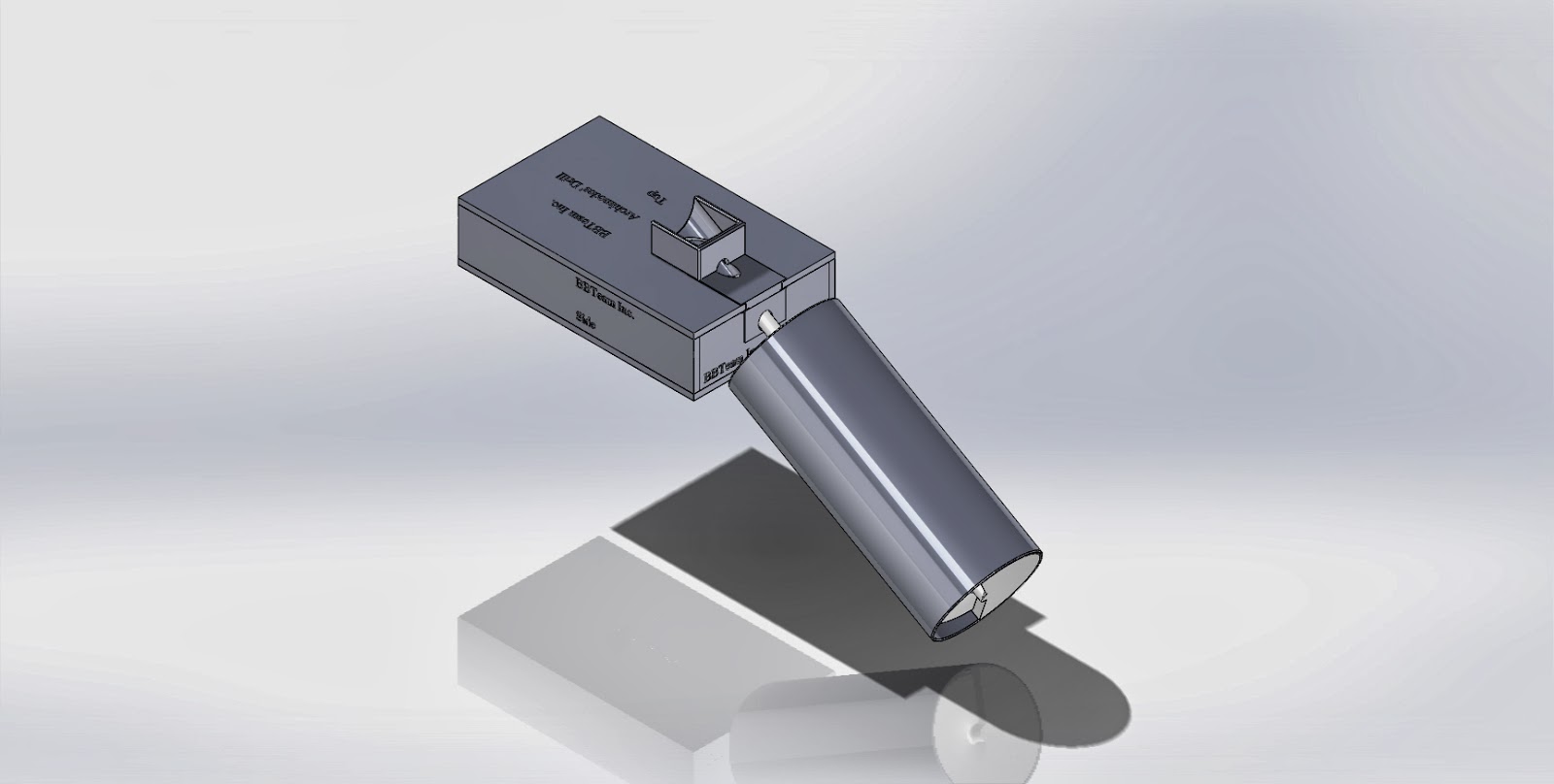
This is the full assembly to be used in our project. Several laser cut parts were used to construct a box with angled holes to fit the shaft of the screw head through. A new case for the DC motor was also designed to accommodate the new base.
link:
Figure 1. Full Assembly
This is an exploded view of the full assembly
From this view all of the laser cut parts can be seen, as well as two small printed parts designed to slide into the cutouts in the top and front piece of the base to allow the drill to be positioned at the proper angle. These printed parts, seen below, were necessary because the laser cutter is not capable of making cuts at an angle, as was required, only vertically.
link:
link:
Figure 2: Front hole cutout
link:
link:
Figure 3: Top hole cutout
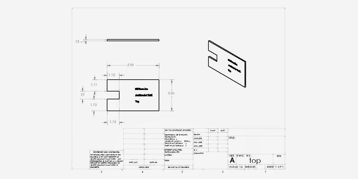
The following parts were designed to be laser cut out of 1/8 inch acrylic in order to make the base seen in the assembly.
link:
link:
Figure 4: Base top
link:
link:
Figure 5: Base bottom
link:
Figure 6: Base side
link:
link:
Figure 7: Base front
link:
link:
Figure 8: New case for DC Motor
This is a short clip of how the drill will run inside the case once the DC motor is connected to it.
And we got our drill printed out! It was printing for 25 hours.
This week we met twice, the first time for about two hours and then again for another hour and a half.


.JPG)
+drawing.JPG)
.JPG)
+drwing.JPG)


No comments:
Post a Comment