Project by BBteam

Project by BBteam

Thursday, December 12, 2013

Problems encountered

As the project deadline approaches we realized that we would not be able to actually be able to assemble and run our design as planned, as we were missing numerous parts, both printed and laser cut.

We were able to get the code and circuit set up with the Arduino board and everything seemed to function as planned. It did seem however that the board was not able to supply sufficient power to both the DC and servo motors, as the DC ran much slower than it did without the servo attached.


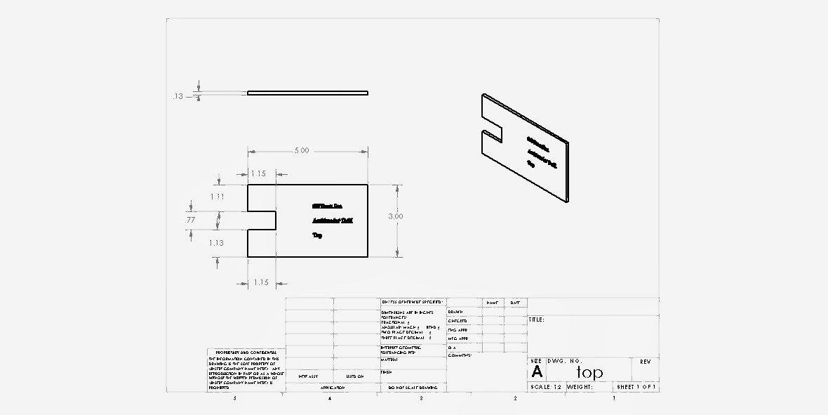
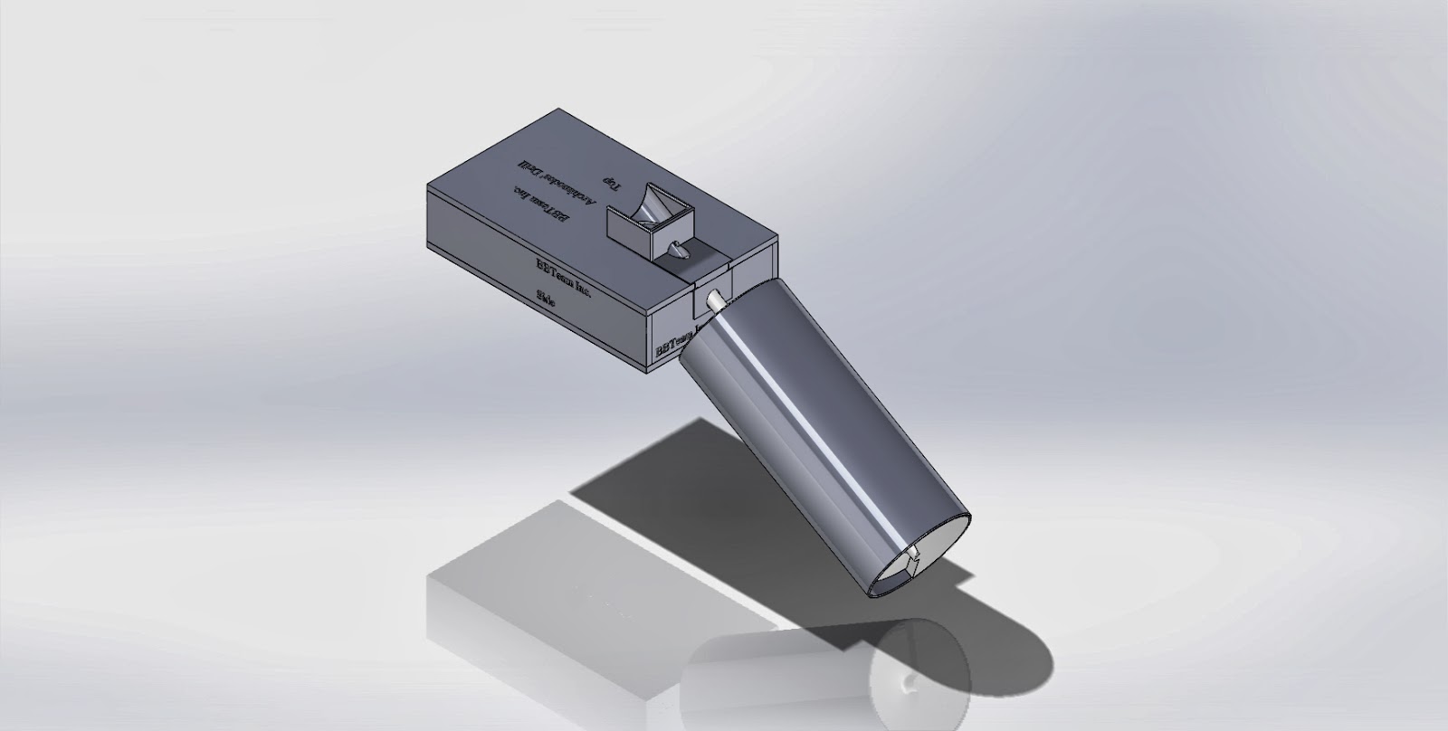
We received the two printed pieces designed to be slid into the top and front sections of the base, as well as the old DC housing design. We did not get the screw housing or the new DC housing, both of which were critical parts to actually make our design function. As far as laser cut parts we only received one side piece and the bottom piece, so we were unable to construct the base.


 This week all group members met and spent approximately 3 hours working on the project.

Monday, December 9, 2013

Updates

Hey People! We made updates in our project. We designed a case for whole system and an inclined case for DC Motor, which allows us to keep a motor in the same angle as the drill. Also, here is the video of the moving spiral (cool, right?!)

This is the full assembly to be used in our project. Several laser cut parts were used to construct a box with angled holes to fit the shaft of the screw head through. A new case for the DC motor was also designed to accommodate the new base.
link:
Figure 1. Full Assembly

This is an exploded view of the full assembly

From this view all of the laser cut parts can be seen, as well as two small printed parts designed to slide into the cutouts in the top and front piece of the base to allow the drill to be positioned at the proper angle. These printed parts, seen below, were necessary because the laser cutter is not capable of making cuts at an angle, as was required, only vertically.

link:

link:
Figure 2: Front hole cutout


link:

link:

Figure 3: Top hole cutout

The following parts were designed to be laser cut out of 1/8 inch acrylic in order to make the base seen in the assembly.

link:

link:

Figure 4: Base top

link:

link:

Figure 5: Base bottom


link:

Figure 6: Base side

link:

link:

Figure 7: Base front


link:

link:

Figure 8: New case for DC Motor

This is a short clip of how the drill will run inside the case once the DC motor is connected to it.


And we got our drill printed out! It was printing for 25 hours.


This week we met twice, the first time for about two hours and then again for another hour and a half.

Wednesday, December 4, 2013

PROgress

Hi everybody! BBTeam presents the solidworks parts, assembly and the arduino code, which is going to run the stuff around!:) Enjoy!!

This is the primary component of the Archimedes' drill. The screw design traps water as it rotates and carries it upwards towards the top.
link:

link:
Part 1. Archimede's drill

This part serves a sheath or case for the screw. It traps the water as it is carried upwards to prevent it from spilling out.
link:

link:
Part 2. Case for the drill

This part is designed to hold the DC motor in place as it rotates the screw.
link:

link:
Part 3. Case for a DC Motor

This shows a cross section of the assembly made from the screw and screw casing. When rotating this will ideally be facing upwards at approximately a 30 degree angle.


link:

link:
Assembly (Archimede's Drill)

Arduino code

The code allows the drill to be controlled. The drill speed is governed by the potentiometer, while the servo motor is controlled by the pushbutton. The code may be edited later to incorporate an LCD screen and possibly try to automate the servo function with a timing code.

For this meeting Brendan, Mike, Iasha, and Eric were all in attendance during the meetings this week. In total we spent about two and a half hours

Saturday, November 16, 2013

Hey people!

Our project is going on! We had couple meetings and figured out the final idea of the project. So, the main part - drill - will be designed and print in the SolidWorks. The DC motor will be attached to the drill, so it will pump the water from the bottom reservoir up to the top. The potentiometer will control the speed of the DC motor. Also, LCD display will display the speed of rotation of the drill. And finally, the Servo motor will be attached to the top cup (reservoir) and flip it, so the water goes back to the bottom reservoir, when the button is pushed!

During the meetings this week we spent about one hour brainstorming.

Have fun! Peace

Monday, November 4, 2013

Hey people!

This is a BBteam with a Archimed's drill project.

Hopefully, you are doing good, and we will try to surprise you in our every post over.

Here is a our projected result, which we will design by SolidWorks 2013, print out model with a 3D printer and use Arduino Board to demonstrate the motion.

Peace:)